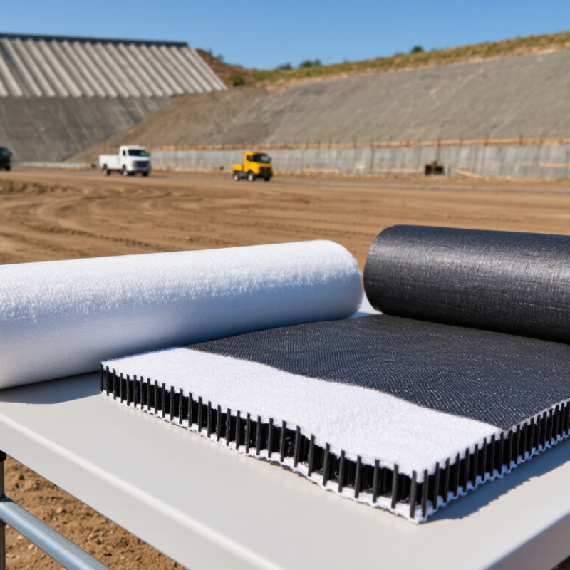
Choosing Geo Synthetic Materials is not a catalog exercise. It is a site-specific engineering decision.
Market intelligence reports show continued demand for these materials. MarketsandMarkets estimates the global geosynthetics market could reach approximately USD 18 billion by 2028. Grand View Research reports similar long-term growth, although its market boundaries differ. These differences matter. Reported figures should guide planning, not replace design judgment.
A reliable selection begins with the material’s function. A needle-punched geotextile may separate weak subgrade beneath a construction road. A textured geomembrane may control leakage on a steep landfill slope. A geocomposite drain may move water behind a retaining wall. Each application demands different tensile strength, puncture resistance, permeability, chemical durability, and interface friction.
Robert M. Koerner, a leading geosynthetics researcher and founder of the Geosynthetic Research Institute, is often quoted as saying, “There are no bad geosynthetics, only bad applications.” His principle remains practical. The wrong product can fail beside a correct-looking design.
The Federal Highway Administration’s Geosynthetic Design and Construction Guidelines emphasize site investigation, material testing, installation control, and long-term performance. ASTM standards also provide procedures for testing properties such as mass per unit area, seam strength, and hydraulic conductivity. These documents offer authority, but field conditions still create uncertainty.
Consider wet clay, sharp aggregate, intense sunlight, or repeated vehicle loading. Small details can control performance. A specification based only on price may look efficient initially. It may become expensive after wrinkles, clogged drains, or seam defects appear.
The better question is not, “Which product is strongest?” It is, “Which verified material performs its required function under actual site conditions?” That answer sometimes remains imperfect. Good engineering acknowledges that limitation.
Choosing geosynthetic materials starts with the soil, water, load, and installation conditions. Geotextiles separate weak subgrades from aggregate and filter moving water. Geomembranes provide low-permeability containment for ponds, landfills, and irrigation reservoirs. Geogrids reinforce roads, retaining walls, and working platforms. Geocomposites combine drainage and filtration layers.
A 2024 Grand View Research report estimates the global geosynthetics market at over 14 billion US dollars in 2023, with continued growth through 2030. This expansion reflects practical demand, not fashion. The Federal Highway Administration identifies separation, filtration, drainage, reinforcement, protection, and containment as core geosynthetic functions. On a muddy access road, a woven geotextile can prevent aggregate from disappearing into the subgrade. In a capped landfill, a drainage composite can guide rainwater away from the barrier layer.
Material selection still requires field judgment. I once focused too heavily on tensile strength and overlooked puncture risk during placement. That was a specification weakness. Designers should check survivability, aperture size, permeability, friction, seam performance, ultraviolet exposure, and chemical compatibility. A high-strength geogrid may perform poorly if soil interaction is ignored. A geomembrane may fail when wrinkles, temperature, or subgrade movement receive little attention. The 2023 International Geosynthetics Society technical guidance stresses design verification and construction quality control. Laboratory data helps. Site evidence matters more. Test seams, inspect overlaps, and record actual soil conditions before installation.
Choosing geosynthetics begins with the ground, not the product catalog. Record soil type, moisture, groundwater, slope angle, traffic loading, and construction access. A soaked subgrade may behave very differently from a dry laboratory sample. Test CBR, particle size, shear strength, pH, and permeability where failure consequences are serious. FHWA’s Geosynthetic Design and Construction Guidelines emphasize site investigation, drainage, installation control, and long-term compatibility.
Small details matter. A torn separator can allow aggregate contamination within hours. Poor anchorage can wrinkle a liner before rainfall arrives. For weak roadbeds, select geotextiles or geogrids according to tensile strength, aperture, puncture resistance, and filtration performance. FHWA’s Geosynthetic Reinforced Soil guidance reports more than 200 U.S. GRS-IBS structures by the mid-2010s, showing that measured construction quality supports repeatable performance. The number is useful, but it does not replace project-specific testing.
Exposure conditions also control material selection. Check ultraviolet exposure, chemical contact, freeze-thaw cycles, biological activity, and expected service life. USACE EM 1110-2-1902 stresses evaluating seepage, consolidation, and slope stability together, rather than treating reinforcement as an isolated layer. No checklist is perfect. Designers sometimes overtrust manufacturer data, while field drainage receives too little attention. Inspect overlaps, seams, wrinkles, and cover thickness during installation. Then compare field observations with the original design assumptions before approving the next construction stage.
Sources: FHWA, Geosynthetic Design and Construction Guidelines; FHWA, Geosynthetic Reinforced Soil-Integrated Bridge System guidance; USACE EM 1110-2-1902.
Matching Geosynthetic Properties to Soil, Loads, and Environmental Factors
Choosing geosynthetic materials starts with the soil, not a product catalogue. Soil gradation, moisture, shear strength, and drainage behavior define the main risk. A soft, saturated subgrade may need separation and filtration before reinforcement. Fine particles can migrate through poorly selected openings. Field probing and laboratory gradation tests should support the design. Visual inspection alone is unreliable.
Loads determine the required mechanical properties. Under a haul road, tensile strength, junction stability, puncture resistance, and creep matter. For a landfill cover, low permeability and interface shear strength may control performance. Temporary construction loads can exceed final design loads. That detail is often missed. Use factors for installation damage, seams, aging, and uncertainty. Do not treat a datasheet value as field capacity; test results depend on methods and specimen conditions.
Environmental exposure can change the choice again. Ultraviolet light, freeze-thaw cycles, high temperatures, saline water, and chemicals require durability checks. Drainage layers need enough transmissivity after compression, not merely when unloaded. On site, sharp aggregate and careless placement can damage suitable material. Field teams often discover this too late. Inspection records, seam checks, and sample testing add practical reliability. Some projects need more investigation, not more material.
Selecting geosynthetics starts with site evidence, not a product catalogue. Soil gradation, groundwater, slope angle, loading, and ultraviolet exposure shape the decision. A woven geotextile may provide tensile separation beneath a haul road, while a nonwoven layer supports drainage and filtration. Geogrids improve aggregate confinement, but they cannot replace proper compaction. For ponds or containment areas, geomembranes demand compatible seams and careful subgrade preparation. Small punctures matter.
Installation requirements often control the real budget. Crews need clean, level surfaces, correct overlap widths, and protection from sharp stone. Wet weather can turn simple placement into a delay. On one road project, poor edge anchoring caused wrinkles and rework. The material was suitable, but the installation plan was not. That experience still influences my specifications. I now require trial panels, seam testing where applicable, and photographic inspection records.
Lifecycle cost deserves more attention than purchase price. A thicker barrier may reduce leakage risk and repairs, while a stronger reinforcement layer can lower aggregate thickness. However, overdesign also wastes money and complicates handling. Costs accumulate. Estimate transport, labor, drainage outlets, inspections, repair access, and eventual replacement. Use project-specific test data and qualified engineering review. Some assumptions will be wrong. Revise them when field measurements disagree. Record expected service life, damage tolerance, maintenance frequency, and disposal constraints, not just dollars per square meter.
Choosing geosynthetics starts with design compliance, not catalog comparison. I check soil chemistry, tensile demand, drainage gradients, temperature, and installation access. A bridge approach may need reinforcement. A landfill liner needs containment and seam control. The FHWA Geosynthetic Reinforced Soil Integrated Bridge System guide reports construction-cost reductions of 25–60% on documented projects. It also reports construction-time reductions of 50–80%. These figures are not universal. Site conditions can erase them.
Require a traceable compliance matrix. It should match each property with a test method, frequency, and acceptance value. For geomembranes, review thickness, tensile strength, puncture resistance, carbon-black dispersion, and stress-crack resistance. ASTM D6392 supports destructive seam testing. ASTM D4437 covers nondestructive seam testing. Factory certificates help. They are not independent verification. Sample rolls by production lot, preserve chain of custody, and compare results against the specification. Small details matter.
Long-term performance requires evidence beyond initial strength. Evaluate creep, oxidation, hydrolysis, ultraviolet exposure, clogging, and chemical compatibility. Use project-specific durability models, not generic service-life promises. The ASCE 2021 Infrastructure Report Card noted that 43% of U.S. public roads were in poor or mediocre condition. That pressure encourages faster construction, but speed can weaken quality control. I still treat the first design as provisional. Field moisture, wrinkles, and imperfect seams can change the expected outcome. Independent inspection, calibrated equipment, and documented corrective actions remain essential.
Selection should be based on the required function, site conditions, verified test data, installation controls, and the design life of the project. Values below are typical guidance ranges and must be confirmed against project specifications and applicable standards.
| Geosynthetic Material | Primary Function | Typical Project Applications | Key Properties to Verify | Typical Performance Range or Design Consideration | Relevant Test Methods or Standards | Long-Term Performance Risks | Selection Check |
|---|---|---|---|---|---|---|---|
| Geotextile | Separation, filtration, drainage, reinforcement, or erosion control | Road subgrades, railway foundations, drainage trenches, retaining structures, coastal works, and erosion-control systems | Mass per unit area, tensile strength, elongation, puncture resistance, apparent opening size, permittivity, and transmissivity | Use a nonwoven geotextile when filtration and drainage are dominant; use a woven geotextile when higher tensile strength and separation are required. Filter opening size must be compatible with the surrounding soil. | ASTM D4595 or ISO 10319 for tensile properties; ASTM D4751 for apparent opening size; ASTM D4491 for permittivity; ASTM D4716 for transmissivity | Clogging, installation damage, ultraviolet exposure before covering, chemical degradation, and loss of drainage capacity under compression | Confirm soil gradation, hydraulic conditions, survivability requirements, and required filtration criteria. |
| Geogrid | Soil reinforcement and load distribution | Mechanically stabilized earth walls, reinforced slopes, pavement base reinforcement, working platforms, and embankments over weak soil | Junction strength, tensile strength, tensile stiffness, aperture geometry, resistance to installation damage, and interaction with aggregate or soil | Performance depends on aggregate interlock, confinement, loading direction, and strain level; short-term tensile strength alone is not sufficient for design. | ASTM D6637 or ISO 10319 for tensile properties; ASTM D7737 for junction strength; project-specific installation-damage and pullout testing where required | Installation damage, creep under sustained load, stress cracking, chemical exposure, and inadequate anchorage or pullout resistance | Verify design tensile stiffness, connection or junction strength, pullout resistance, and reduction factors for creep and damage. |
| Geomembrane | Liquid or gas barrier and containment | Landfill liners and covers, mining leach pads, wastewater ponds, irrigation reservoirs, secondary containment, and hazardous-liquid storage | Thickness, tensile strength, elongation, tear resistance, puncture resistance, seam strength, stress-crack resistance, and permeability | Typical polymer options include HDPE, LLDPE, PVC, and flexible polypropylene. Material selection must match chemical exposure, temperature, subgrade conditions, and required service life. | ASTM D6693 or ISO 527 for tensile properties; ASTM D1004 for tear resistance; ASTM D4833 for puncture resistance; ASTM D6392 or ISO 15221 for seam strength; ASTM D5885 for stress-crack resistance | Seam defects, puncture, differential settlement, thermal expansion and contraction, oxidation, stress cracking, and prolonged ultraviolet exposure | Require a documented welding plan, trial seams, non-destructive seam testing, destructive sampling, and final leak detection where applicable. |
| Geosynthetic Clay Liner (GCL) | Low-permeability hydraulic barrier | Landfill caps and liners, canals, ponds, secondary containment, and composite liner systems | Bentonite mass per unit area, swell index, fluid loss, hydraulic conductivity, peel strength, and internal shear strength | Hydraulic conductivity is commonly designed at approximately 1 × 10⁻¹¹ m/s or lower when properly hydrated and confined; actual performance depends strongly on the permeant and installation conditions. | ASTM D5887 for hydraulic conductivity; ASTM D5890 for swell index; ASTM D5891 for fluid loss; ASTM D6496 for peel strength | Premature hydration, desiccation, bentonite compatibility with saline or contaminated liquids, wrinkles, overlap displacement, and poor confinement | Protect from rain and uncontrolled hydration, confirm chemical compatibility, and provide adequate overlap and confinement. |
| Geocomposite Drainage Layer | In-plane drainage and fluid conveyance | Landfill covers, retaining walls, foundation drainage, road drainage, tunnel waterproofing protection, and vertical drainage systems | Transmissivity, compressive resistance, interface friction, filter compatibility, core thickness, and resistance to installation damage | Drainage capacity must be checked at the design normal stress, hydraulic gradient, temperature, and anticipated reduction over the service life. | ASTM D4716 for transmissivity; ASTM D1621 or project-specific compression testing; ASTM D5321 for interface shear; ASTM D4751 for filter opening size where a geotextile filter is included | Crushing or creep of the drainage core, filter clogging, blocked outlets, inadequate slope, and reduced flow under long-term compression | Calculate flow capacity using site-specific compressive stress and include an appropriate reduction factor for clogging and creep. |
| Geocell | Lateral confinement, load distribution, and erosion control | Unpaved roads, slope protection, channel lining, access roads, embankment reinforcement, and low-volume traffic areas | Cell depth, cell size, strip tensile strength, seam strength, aperture stability, anchorage, and infill compatibility | Performance is governed by cell confinement, infill quality, anchorage, and surface drainage. It is not a substitute for proper subgrade preparation or structural drainage. | ASTM D4883 for geocell seam or strip strength where applicable; ASTM D6637 for polymeric tensile properties; project-specific pullout and load-spreading tests | Seam failure, ultraviolet degradation before cover, infill migration, inadequate anchorage, and erosion at unprotected transitions | Verify cell geometry, seam strength, anchorage pattern, infill gradation, and surface-water management. |
| Erosion-Control Geosynthetic | Surface erosion protection and vegetation establishment | Channels, cut slopes, embankments, drainage swales, riverbanks, and temporary construction slopes | Open area, tensile strength, shear resistance, UV stability, permissible shear stress, anchorage, and vegetation compatibility | Temporary blankets are selected for the expected establishment period; permanent systems must be checked against design flow velocity, shear stress, and exposure duration. | ASTM D6818 for tensile properties of rolled erosion-control products; ASTM D6460 for large-scale rainfall or channel performance; manufacturer-independent project testing where needed | Uplift, undercutting, UV degradation, poor soil contact, insufficient anchorage, and damage from concentrated flow | Match the system to calculated hydraulic shear stress and install anchors, overlaps, and termination details exactly as designed. |
| Paving Fabric or Asphalt-Reinforcement Geosynthetic | Interlayer separation, crack reduction, and moisture control in pavement rehabilitation | Asphalt overlays, pavement rehabilitation, reflective-crack mitigation, and waterproofing beneath asphalt layers | Tensile strength, asphalt retention, melting or softening behavior, adhesion, puncture resistance, and installation temperature compatibility | Results depend on pavement condition, crack movement, surface preparation, tack coat, overlay thickness, and drainage. It cannot correct structural failures caused by unstable subgrade. | ASTM D6637 for tensile properties; ASTM D6140 for asphalt retention; project-specific interlayer bonding and reflective-crack testing | Debonding, wrinkling, inadequate tack coat, construction damage, moisture trapped beneath the overlay, and excessive crack movement | Repair failed pavement areas first, confirm surface dryness and bond requirements, and control paving temperature and placement. |
| Fiberglass or Polymer Geocomposite Reinforcement | Tensile reinforcement and crack-control support | Asphalt overlays, bridge approaches, industrial pavements, and localized structural rehabilitation | Longitudinal and transverse tensile strength, stiffness, bond strength, creep, alkali resistance where relevant, and installation survivability | Use design strains and loading cycles rather than nominal tensile strength alone. Reinforcement must be fully bonded and placed at the specified elevation within the pavement system. | ASTM D6637 or ISO 10319 for tensile properties; ASTM D5321 for interface shear; project-specific fatigue and reflective-crack testing | Insufficient bond, construction wrinkles, creep, chemical attack, poor overlap detailing, and reinforcement placed outside the effective tensile zone | Verify interface bond, overlap, strain compatibility, fatigue behavior, and construction tolerances. |