Choosing a compact UAV BMS is not just a matter of finding the smallest board. The system must fit the drone’s battery, current draw, and available cooling space. It also needs to report cell voltage and temperature clearly. In a cramped airframe, a connector that presses against a carbon-fiber frame can become a real design problem. Small details matter.
The International Energy Agency’s Global EV Outlook 2024 reported that electric-vehicle battery demand reached about 750 GWh in 2023, roughly 40% above 2022. That figure describes the wider battery market, not UAV packs. Still, it highlights the scale of ongoing battery-system development; it does not prove that a particular BMS suits a drone. Battery scientist Dr. Shirley Meng’s systems-focused research offers a useful perspective: battery performance should be assessed as a whole, rather than by one headline metric. For a UAV, that means looking beyond rated capacity to protection thresholds, balancing, telemetry, and response under flight loads.
A practical comparison should start with the pack’s chemistry, series-cell count, peak current, and physical dimensions. Check whether the BMS supports the drone’s charger and flight controller. Ask how it handles overcurrent, undervoltage, temperature excursions, and cell imbalance. Then inspect the datasheet, wiring diagram, and test conditions. A compact board may save space but add little value if its current rating is marginal or its readings arrive too slowly. That is not enough. The right choice depends on measured flight behavior, not a product label alone. A bench test helps, but it cannot reproduce every vibration, temperature swing, or rapid throttle change. Leave room for uncertainty, and verify the system in the intended aircraft.
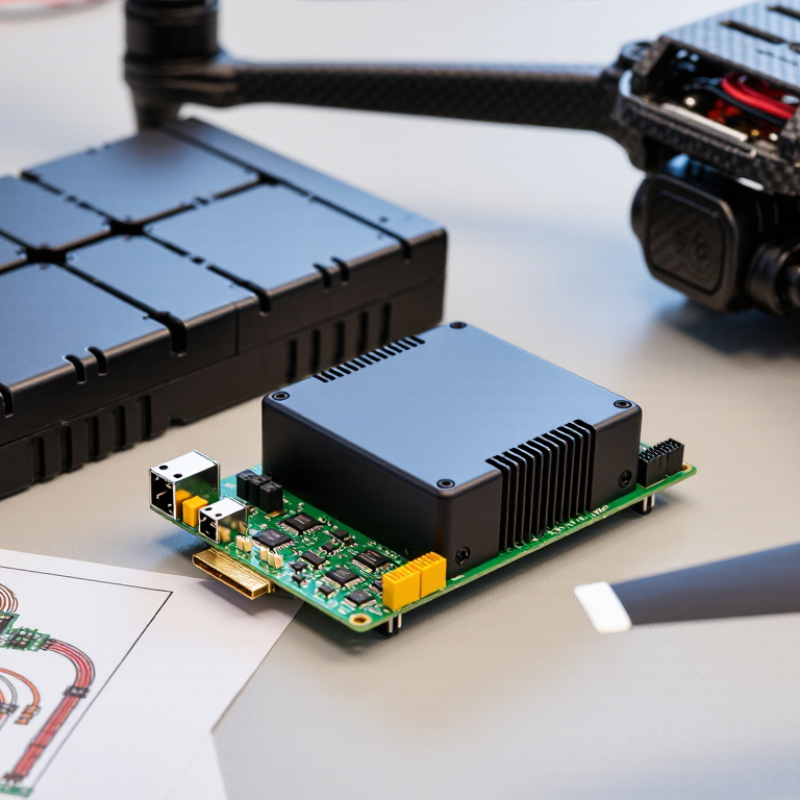
A compact UAV’s BMS should be sized around its actual flight profile, not its advertised endurance.
Record the battery voltage, average current, takeoff peaks, payload, and expected flight time. A motor may draw modest current while hovering, then demand a sharp surge during climb. Measure it in flight.
Include cold starts and warm battery compartments; both can change available capacity and sensor readings. The IEA’s Global EV Outlook 2024 reports more than 750 GWh of battery demand in 2023, roughly 40% above 2022. That growth reflects a broad supply chain, not a guarantee that a small UAV pack will meet a particular current or energy-density figure.
Estimate required energy in watt-hours, then check whether the chosen cell configuration can deliver it without excessive voltage sag.
The U.S. Department of Energy’s Battery500 program sets a 500 Wh/kg cell-level target; it is a research target, not a dependable pack specification. Cells, wiring, casing, and the BMS add mass. Leave room for them.
Check the BMS’s continuous and peak current ratings against measured motor loads, and confirm its voltage limits match the cell series count. Review temperature sensing, balancing, and low-voltage cutoff behavior.
One caveat: bench tests may miss brief in-flight peaks, so validate the setup with logged flight data before fixing the design.

Choose a compact UAV BMS around the cell chemistry, not the other way around. Lithium-polymer packs can deliver sharp current bursts, so verify that the BMS’s continuous and peak-current limits match motor demand. Lithium iron phosphate has a different voltage profile; use chemistry-specific overvoltage and undervoltage thresholds. A generic cutoff can waste usable capacity or leave cells exposed.
Flight conditions matter just as much. Cold air can raise cell resistance and reduce available power, especially during a fast climb. Place temperature sensing near the cells, not beside a warm processor, and confirm the BMS can flag voltage sag under load. For hot, enclosed fuselages, check sensor coverage and thermal limits. Small, but critical. A few grams saved are not worth blind spots in protection.
The International Energy Agency’s Global EV Outlook 2024 reports that LFP supplied about 40% of global electric-car battery demand in 2023. That is useful chemistry context, not proof of UAV performance: drone packs face different discharge peaks, vibration, and cooling. Compare BMS logging against real flight data, including takeoff current and landing temperature. One trade-off is easy to miss: a highly conservative cutoff may protect cells but trigger early landings. Test it with the actual pack. Cold changes everything.
A compact UAV battery management system (BMS) should fit the aircraft, not just the battery label. Measure the available bay, connector clearance, wire bend radius, and mounting space before choosing a board. A few millimeters can obstruct a cover or press against insulation. Keep mass low, but do not remove protective features to save grams. Compare the complete installed weight, including cables, fasteners, and any heat spreader. Easy to miss.
Check cell-count compatibility, current limits, balancing method, and protection against overcharge, over-discharge, short circuits, and excessive temperature. Ask for test data at the pack’s expected current, not only a headline rating. In a drone, airflow changes with propeller speed and enclosure shape. Test near the battery under realistic loads, then inspect temperatures at the hottest point. Leave clearance around heat-producing components; avoid burying them in foam. A sensor far from the cells may show a reassuring reading while missing a local hot spot. Thermal estimates are imperfect. Vibration, moisture, and repeated charging can also loosen connections or reveal weak insulation. If measurements are uncertain, reduce the operating load and retest.
A compact UAV BMS should exchange data in a format your flight controller can read. Check the supported interface, such as UART or CAN, and verify the required protocol and baud rate. A matching plug does not guarantee compatible data. Small details matter. Confirm which values the BMS reports, including pack voltage, current, temperature, and state of charge.
A practical bench test can reveal problems before the battery goes into the airframe. Connect the BMS and controller, then compare displayed readings with a reliable meter. Watch for delayed updates, missing fields, or error messages when the load changes. Test it on the bench. If telemetry pauses during a brief current spike, the wiring, settings, or data rate may need attention.
Monitoring is useful only when the readings support clear decisions. Check whether alarms can flag low voltage, excess temperature, or abnormal current, and learn how the controller responds to each alert. Review connector pinouts and firmware settings carefully; a reversed signal wire can waste an afternoon. It happens. Also consider the BMS’s size and cable routing inside the drone. A compact unit may fit neatly, yet leave too little room for airflow or secure strain relief. Recheck compatibility after firmware updates, since communication behavior can change. Don’t assume a successful startup proves the full setup works.
| How to Choose a Compact UAV BMS for Your Drone? — Check Communication, Monitoring, and Flight Controller Compatibility | |||
|---|---|---|---|
| Selection Dimension | What to Check | Practical Verification | Why It Matters |
| Cell Count and Battery Chemistry | Confirm the supported series cell count and chemistry, such as Li-ion or LiPo. Do not assume that voltage limits are identical across chemistries or battery specifications. | Match the BMS cell-count setting to the pack. Check the battery and BMS documentation for per-cell charge, discharge, and cutoff limits. | The BMS must measure and protect every series cell within the limits specified for the battery. |
| Current Rating | Check continuous and peak discharge ratings, along with peak duration and thermal conditions. The BMS rating must suit the aircraft’s maximum expected load. | Compare the BMS rating with measured or calculated worst-case current, including motor and payload demand. Allow for wiring, connector, cooling, and altitude constraints. | An undersized BMS may overheat or disconnect during high-load flight; a rating alone does not guarantee performance in every installation. |
| Voltage and Power Path | Verify the BMS operating-voltage range, charge and discharge path, and whether its output is common-port or separate-port. | Check the power schematic and confirm that the charger, battery, ESCs, and any power module are connected to the intended terminals. | Incorrect port wiring or voltage limits can prevent charging, interrupt power, or damage connected equipment. |
| Communication Interface | Identify the available interface, such as UART or CAN, and confirm protocol, connector pinout, baud rate, and electrical signal levels. | Check that the flight controller supports the BMS protocol—not just the physical connector. Verify signal voltage compatibility before connecting. | UART and CAN are not automatically interchangeable, and devices using the same interface may still use different protocols or pinouts. |
| CAN Bus Integration | For CAN-connected systems, verify the supported message format, bitrate, node configuration, and termination requirements. | Consult both device manuals. A CAN bus typically requires 120-ohm termination at each physical end of the bus; avoid adding unnecessary terminators. | Correct bus setup helps prevent communication errors and allows the flight controller to receive battery data reliably. |
| Battery Monitoring Data | Check which values are reported, such as pack voltage, current, individual cell voltages, temperature, state of charge, and fault status. | Confirm that the flight controller can display or log the required fields, and compare reported voltage and current with a suitable meter during bench testing. | Useful telemetry supports low-battery warnings, flight planning, and troubleshooting. Reported state of charge depends on the BMS method and battery configuration. |
| Protection and Recovery | Review overvoltage, undervoltage, overcurrent, short-circuit, and temperature protections, including recovery behavior after a fault. | Use the manufacturer’s documented test procedure; do not deliberately trigger hazardous faults on a flight-ready battery. | Protection thresholds and reset behavior affect whether a fault is safely managed or causes an unexpected loss of power. |
| Flight Controller Compatibility | Confirm supported firmware, battery-monitor configuration, connector pinout, data scaling, and any required parameter settings. | Bench-test telemetry and alarms with propellers removed. Verify that voltage, current direction, and battery capacity readings are plausible. | A compatible connector does not ensure compatible data. Incorrect scaling or configuration can produce misleading battery estimates. |
| Size, Mass, and Thermal Design | Check board dimensions, mounting holes, cable clearance, mass, airflow, and operating-temperature limits. | Measure the available installation space and assess heat dissipation in the actual enclosure and expected flight environment. | A compact board still needs secure mounting, adequate insulation, and suitable cooling for its current and operating conditions. |
| Preflight Acceptance Checks | Confirm correct cell count, balanced cell readings, secure connections, valid telemetry, and functioning low-battery and fault alerts. | Perform ground tests according to the battery and aircraft procedures, then recheck wiring and configuration before flight. | System-level checks can reveal wiring, configuration, or communication problems before the aircraft is airborne. |
A compact UAV BMS should be judged by field reliability, not board size alone. Check whether it records cell voltage, pack current, and temperature during vibration and rapid throttle changes. A small connector can loosen after repeated landings. Ask for test conditions and fault logs, not just a reliability claim.
The UN Manual of Tests and Criteria, subsection 38.3, defines eight tests for lithium battery transport qualification. Its thermal test includes ten cycles between 72°C and −40°C. Useful evidence. But passing these tests does not prove the BMS will perform well in your aircraft or certify the whole UAV.
For integration, confirm voltage and current limits, communication protocol, connector pinout, and alarm behavior before installation. Then test the BMS with the actual motors and payload; electrical noise can expose faults that a bench setup misses.
Certification scope matters. A transport test report is not an operational approval. For maintenance, make sure technicians can review cycle counts, temperature events, and cell imbalance without removing the pack.
Set service limits using the cell supplier’s data and flight records, not guesswork. One trade-off deserves a second look: adding diagnostics can improve fault tracing, yet extra wiring adds failure points. That detail is easy to overlook.